
#PLC Series 6.0: A-Z PLC Terminologies for #Industrial #Engineers
#Actuator – An output device normally connected to an output module. Examples are an air valve and cylinder.
#Branch – A parallel #logic path within a #rung.
#Coil – Represents the output of a programmable logic controller. In the output devices, it is the #electrical coil that, when #energized, changes the status of its corresponding contacts.
#Data Highway – A communications network that allows devices such as PLCs to communicate. They are normally #proprietary, which means that only like devices of the same #brand can communicate over the highway.
#Electrical #Optical Isolator – A device that couples input to output using a semiconductor light source and detector in the same package.
#Fixed I/O – Input/output terminals on a programmable logic controller that are built into the unit and are not changeable. A fixed I/O PLC has no removable #modules.
Glitch – A voltage or #current spike of short duration that adversely affects the operation of a PLC
Host Computer – A main computer that controls other computers, PLCs, or computer peripherals.
Input Devices – Devices such as limit switches, pressure switches, pushbuttons, and analog and/or digital devices that supply data to a programmable logic controller#Input Devices – Devices such as #limit switches, #pressureSwitches, #pushbuttons, and #analog and/or digital devices that supply data to a programmable logic controller#non.
Jump Instruction – is a type of instruction that permits the bypassing of selected portions of the user program. Jump instructions are conditional whenever their operation is determined by a set of preconditions and unconditional whenever they are executed to occur every time they are programmed.
k – #Kilo; a prefix used with units of #measurement to designate quantities 1000 times as great.
#Ladder Diagram Programming – A method of writing a user program in a format similar to a relay ladder diagram.
Master control relay (#MCR) – A mandatory #hardwired relay that can be de-energized by any series-connected #emergencystop switch. Whenever the master control relay is de-#energized, its contacts open to de-energize all application input and output devices.
#Non-volatile Memory – is a type of #memory designed to retain its data while its power supply is turned off.
#Output device – Any connected equipment that will receive information or instructions from the central processing unit, such as control devices (e.g., #motors, #solenoids, #alarms) or #peripheral devices (e.g., line printers, disk drives, displays). Each type of output device has a unique interface to the processor.
#Program Scan – is one of three parts of the PLC scan. During the program scan, the CPU scans each rung of the user program.
#Response time – The amount of time required for a device to react to a change in its #input signal or to a request.
#Status indicators – LEDs that indicate the on-off status of an input or output point and are visible on the outside of the PLC.
#TT L-input module – Enables devices that produce TTL-level signals to communicate with a #PLC’s processor (TTL denotes Transistor- Transistor Logic)#TTL-input module – Enables devices that produce TTL-level signals to communicate with a #PLC’s processor (TTL denotes Transistor- Transistor Logic)#non.
#Up-Counter – An event that starts from 0 and increments up to the preset value.
#Volatile memory – A memory structure that loses its information whenever power is removed. Volatile memories require a battery backup to ensure memory retention during power outages.
#Work cell – A group of machines that work together to manufacture a product; normally includes one or more# robots. The #machines are programmed to work together in appropriate sequences. Work cells are often controlled by one or more PLCs.
#Zone – The portion of a PLC ladder program that can be enabled or disabled by a #control function.
Source – Frank D. P. (4th Ed.). 2005. Programmable Logic Controller (PLC)
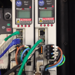
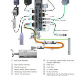
Photo Credit: RealPars