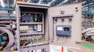
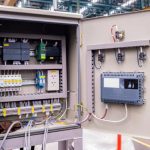
In a control panel powered by a DC supply, proper grounding is essential for ensuring both safety and reliable operation.

Grounding configurations hinge on two distinct concepts:

equipment grounding, which safeguards personnel and equipment, and

system grounding, which stabilizes voltage and minimizes electrical noise.

Want to master these critical aspects of control panel design? Explore the following key topics to gain a comprehensive understanding:
-
Equipment Grounding vs. System Grounding: A Deep Dive into Control Panel Safety
-
Grounding Essentials: Understanding Equipment vs. System Grounding in Control Panels
-
Control Panel Grounding: Comparing Equipment and System Grounding Techniques
-
Wired for Safety: Equipment Grounding vs. System Grounding in Control Panels
-
Mastering Grounding: Equipment vs. System Grounding for Control Panel Design
-
Grounding Unveiled: Equipment vs. System Grounding in Control Panel Engineering
-
Safe Circuits: Exploring Equipment and System Grounding in Control Panels
-
Grounding Matters: A Guide to Equipment and System Grounding in Control Panels
-
Power Protection: Equipment Grounding vs. System Grounding for Control Panel Stability
This blog post will break down these grounding topics in detail, providing you with the knowledge and insights needed to design safer and more efficient control panels with confidence.
How DC Conductors Relate to Grounding in Control Panels
1. Equipment Grounding
Purpose: Equipment grounding protects personnel and equipment by providing a low-resistance path for fault currents, such as those caused by short circuits or insulation failures, preventing electric shocks or equipment damage.
Connection:
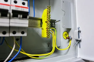
Neither the positive nor negative DC conductor is directly connected to the equipment ground during normal operation. Instead, the equipment ground (typically a green or green/yellow conductor per NEC or IEC standards) is bonded to the control panel’s metal chassis, enclosure, and non-current-carrying metal parts.
This conductor connects to the panel’s grounding busbar, which is tied to the building’s earth ground system.
In a DC system, the power supply’s output (positive and negative lines) is generally isolated from the equipment ground unless a fault occurs or the system is intentionally grounded (see system grounding below).
Key Point: The equipment ground does not carry current under normal conditions—it’s solely for fault protection. It remains separate from the DC conductors unless a fault necessitates current flow to ground.
2. System Grounding
Purpose: System grounding involves intentionally connecting one of the DC power supply’s output conductors (positive or negative) to ground to stabilize the system’s voltage reference, reduce electrical noise, or enhance safety.

Connection:
Negative Grounding (Most Common): In most DC control panel systems, the negative conductor (0V, often labeled as common or GND) is connected to the grounding busbar or earth ground. This creates a grounded system where the negative line serves as the voltage reference point, reducing noise and aiding troubleshooting.
Positive Grounding (Less Common): In specialized applications, such as telecommunications or cathodic protection systems, the positive conductor may be grounded instead. This is less typical in standard control panels but may be required for specific designs.
Floating Systems: In some cases, neither conductor is grounded, resulting in a floating system. This approach is used to prevent ground loops or interference but is less common in standard control panels.

Key Point: Negative grounding is the standard practice in most control panels, establishing the negative conductor as the 0V reference while maintaining its role as a current-carrying conductor in the circuit.
Practical Notes for Control Panel Grounding
Standards and Codes: Grounding practices adhere to standards like the National Electrical Code (NEC) Article 250 in the U.S. or IEC standards globally, ensuring safe and compliant designs.

Wiring:
The equipment grounding conductor (green or green/yellow) connects non-current-carrying metal parts to the grounding busbar.
The negative DC conductor (often blue or black) may be bonded to the grounding busbar for system grounding, depending on the design requirements.

Safety Considerations:
While DC systems pose less shock risk than AC, proper grounding is critical to prevent electrical noise that can disrupt sensitive devices like PLCs or sensors.

Fusing:
The positive conductor is typically fused for circuit protection, while the grounded negative conductor usually is not, as it serves as the system’s reference.

Summary

Equipment Grounding: A separate conductor (green/yellow) ensures fault protection by connecting the panel’s chassis to earth ground, not directly tied to the DC positive or negative conductors.

System Grounding: Typically, the negative conductor is grounded to provide a stable 0V reference, though positive grounding or floating systems may be used in specific cases.

For tailored guidance on your control panel setup (e.g., specific voltage, industry standards like UL 508A, or unique configurations).